Something you want to know about LED light power factor
Taylor
Introduction
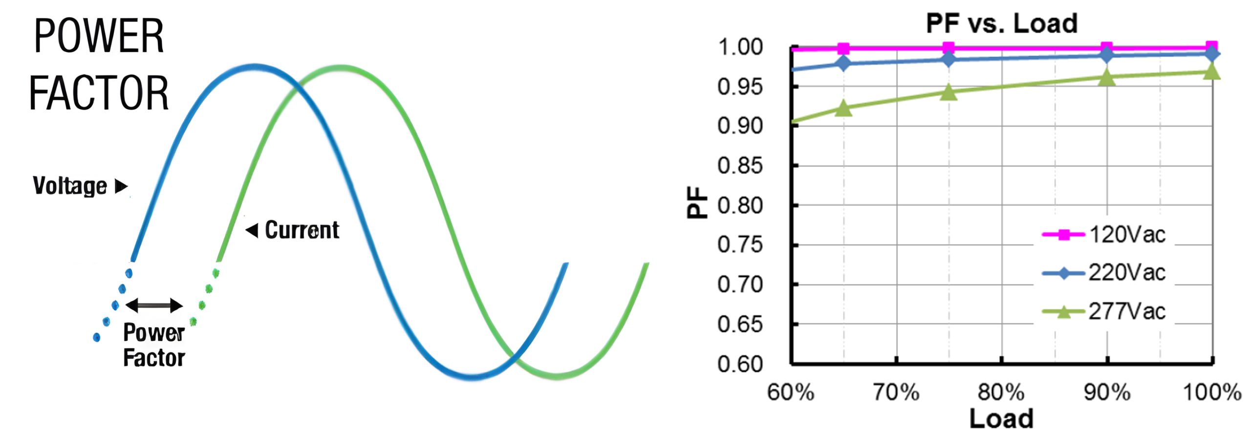
Power factor refers to the ratio between useful power (i.e., the product of voltage and current) and apparent power which is ranged from 0 to 1. Normally the LED light power factor can reach 0.95 or even as high as 0.97 to 0.99, so it does not receive as much attention in the industry as other parameters (such as light efficiency, wattage, lens, etc.). However, there are still some traditional lamps and some LED lamps on the market that have low power factors. These fixtures will cause increased current loads on the mains grid, requiring the use of thicker copper wire to reduce thermal overload and voltage drops on the mains cables, which will lead to increased costs for municipal construction. Although some countries and regions charge extra fees for reactive power, we believe that it is necessary to improve the power factor from the source. Before that, we need to know what power factor is and the importance of power factor. At the same time, we also need to know under what circumstances LED has a better power factor, because LED lamps do not always have a high power factor.
What’s power factor?
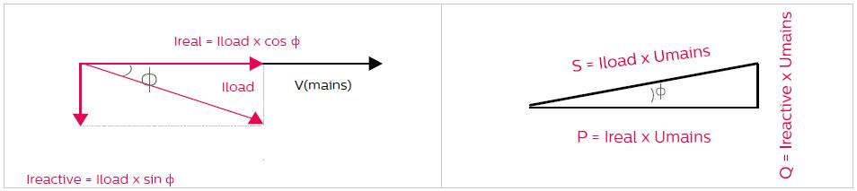
Power factor refers to the ratio between active power (i.e., the product of voltage and current) and apparent power in an AC circuit. It is an important parameter to measure the efficiency of electrical equipment and the quality of the power system. Useful power is the power actually used to perform work in the system, while apparent power is the total power in the system, including useful power and reactive power (power caused by the phase difference between current and voltage, which usually does not perform useful work) . Through the calculation formula of power factor (Power Factor=active power/apparent power), we can know that the value of power factor is between 0 and 1 which includes LED light power factor.
For a purely resistive load, the power factor is equal to 1, which means that the voltage and current are in phase. This means that all the current is used to perform useful work and nothing is wasted. However, for inductive loads (such as motors, transformers, etc.) and capacitive loads (such as capacitors, etc.), the current will lag or lead the voltage, resulting in a part of the electric energy not being effectively utilized, and the power factor will be lower than 1. Low power factor means that the reactive power in the circuit is large, which will increase the power supply loss of the line and reduce the utilization of the equipment. Therefore, improving the power factor helps reduce the power consumption of the power grid and improve the efficiency of equipment and power supply quality. In practical applications, the power factor can be improved through measures such as reactive power compensation and optimization of equipment operation methods.
Why we care about power factor?
Power factor is important in power systems. ZGSM believes that its importance is mainly reflected in the following aspects:
Improve energy utilization: In the absence of power factor correction (when PF is too low), there is a large power loss in the power system. When this useless work flows in the circuit, it will not be directly converted into useful mechanical energy or thermal energy. But they create extra current in electrical equipment. This extra current causes the device’s internal resistance to heat up, which increases the device’s power consumption. On the contrary, the improvement of power factor can reduce the loss of reactive power, thereby improving energy utilization.
Reduce the load on the grid: The improvement of power factor can reduce the reactive power on the grid, thereby reducing the load on the grid. This is crucial for the stable operation of the power system and helps avoid problems such as grid overload and faults. On the contrary, low power factor can cause excessive current in the grid, negatively affecting the stability of the power system.
Affects equipment performance: High power factor can extend the life of electrical equipment and reduce energy waste. When the power factor is too low, a large amount of useless work will be generated in the circuit, which will cause excessive heat in the electrical equipment. Whether it is the equipment of the power grid itself or the electrical equipment, they do not like high temperature environments. Excessively high temperatures will cause accelerated aging of components, resulting in reduced performance or even damage. That is, low PF not only wastes energy, but also causes equipment damage.
Low power factor due to different loads
The reason for low power factor mainly involves the use of inductive components and capacitive components. Equipment is divided into inductive load and capacitive load according to the difference in the number of inductive and capacitive components. Equipment with more inductive components is an inductive load, while equipment with more capacitive components is a capacitive load.
Pure Ohmic load
In addition to inductive loads and capacitive loads, there are also some equipment, electrical appliances and lamps that are purely resistive loads (Pure Ohmic Load). It refers to a load that only contains resistive elements in the circuit. When energized, the circuit only generates heat and light energy and does not convert electrical energy into other forms of energy. In a purely resistive load, the current and voltage change synchronously, that is, they are in the same phase. This means there is no phase difference between current and voltage, so the power factor is equal to 1. A classic example of a purely resistive load is an incandescent lamp. When the lamp is powered on, the electrical energy is mainly converted into heat energy and light energy, where heat energy is generated due to the current passing through the resistance wire. Since the lamp is a purely resistive load, its power factor is close to 1, which means that the lamp can effectively utilize electrical energy and convert it into light/heat without generating a large amount of reactive power. Of course, this does not mean that the light efficiency of incandescent lamps is the highest.
Inductive load
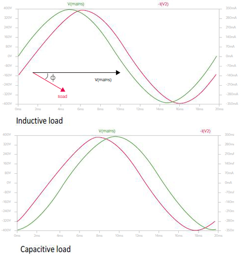
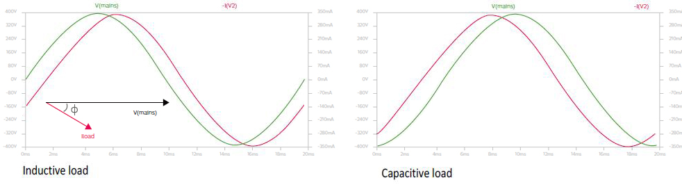
Inductive load refers to a load that contains a large number of inductive components in the circuit, which is one of the main reasons for the low power factor of the equipment. Inductive loads include motors, transformers, and inductors, which generate magnetic fields during operation, causing the current to lag behind the voltage. This hysteresis creates a phase difference between current and voltage, thereby reducing the power factor. We will explain the specific reasons in the next section. A typical example of an inductive load is a HID lamp, whose electromagnetic ballast is inherently inductive, which makes its power factor usually around 0.7 or even lower 0.5. LED lamps also belong to this category, and the power factor of LED lights can reach 0.97.
Capacitive load
Capacitive load refers to a load that contains a large number of capacitive components in the circuit. In contrast to inductive loads, capacitive loads (such as capacitors) cause the current to lead the voltage, thereby increasing the power factor. However, if the capacitive reactance is too large, so that the capacitive reactance is greater than the inductive reactance, then the current will lead the voltage by a larger phase angle, which will also cause the power factor to decrease. Typically, capacitors are added to equipment(LED driver) for reactive power compensation to improve the power factor.
Basic principle refers power factor
In the previous section, we learned that the presence of inductive components and capacitive components in equipment leads to a reduction in the power factor of the equipment, so what is the specific reason? Here we explain the basics in more layman’s terms.
When there are inductive loads in a device (components that generate magnetic fields, such as motors, transformers, and inductors), when current passes through these devices, they create a magnetic field that stores energy. If we imagine the magnetic field as a bucket and the electric current as water, when the faucet is opened, water starts flowing into the bucket, but the bucket does not fill up immediately. This is because the water takes time to flow and fill the bucket. Likewise, when current flows through an inductive load, it creates a magnetic field inside the load, but this magnetic field takes time to build up. This current generated due to the establishment of a magnetic field is called “inductive reaction current”. This current is not actually converted into useful energy for the load, but is stored in the magnetic field. There is a phase difference between this current and the voltage, which means that the voltage has begun to change, but the current has not yet caught up with the change in voltage.
In inductive loads, these components (such as motors) may indeed cause an increase in power consumption from the grid, even though the actual motor does not consume that much power. This is because inductive loads consume reactive power as well as active power. Reactive power is not used directly to do work, but is used to maintain the magnetic field inside the device. Due to the presence of inductive loads, current circulates in the system, causing the total power (apparent power) in the system to increase. Due to the reactive power consumption of inductive loads, the grid needs to provide more current to meet the needs of the equipment. This results in increased power consumption from the grid, even though the actual motor does not consume that much power. Therefore, when designing and operating inductive loads, the impact of reactive power needs to be taken into consideration to improve the efficiency of the equipment and reduce the power consumption of the grid.
Which factors affect power factor in LED lighting?
In the first two sections, we introduced what power factor is, why we care about power factor, and the impact of power factor difference on the power grid. In this section we mainly explain what factors affect the power factor in LED lamps.
Use of inferior power supply
As the main component of lamps, LED power supply has a great influence on the LED light power factor. This is because there are more perceptual components in it than other components of the lamp. However, the LED drivers produced by different power supply manufacturers have greatly different performance in terms of power factor. For example, the power factor of Inventronics‘ EUM series power supply can reach 0.97 or even higher, while the power factor of Done’s MXG series power supply can only reach 0.95. Different series of LED drivers from the same manufacturer also have greatly different power factor performance. For example, the PF of the D4i power supply of EBS-080S105BT2 can reach 0.98.
Unreasonable power supply configuration
The power factor of the same power supply varies greatly in different lamp configurations. The lamp configuration here mainly depends on the matching degree between the load of the lamp and the LED driver. From the table below we can see that the lower the load of the lamp, the worse the PF value. Taking EUM-075S105DG as an example, when the lamp load is 72W (the whole lamp power is 80W) the PF can reach 0.97. If the lamp load drops to 60W, the PF will drop to 0.96. If it continues to drop to 50W, the PF will drop to 0.95 or even lower. The correct approach at this time is to use EUM-050 power supply to drive the corresponding LED module to achieve a better PF value.
Use of dimming function
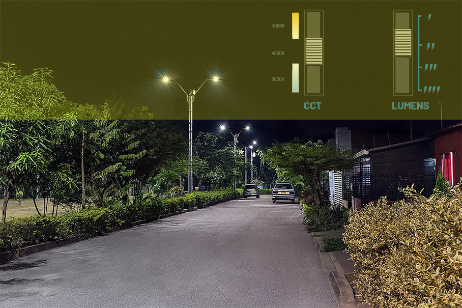
The dimming function in LED lamps is widely used. Although it can save energy, we also need to pay attention to its impact on power factor (PF). In road lighting, LED street lights reduce power after midnight when road traffic decreases to reduce excessive illumination. Another example is that in warehouse lighting, LED industrial and mining lamps will adjust the output according to the space occupied (occupied or unoccupied), thereby reducing unnecessary lighting. Usually, when the lighting demand is low, LED lamps reduce the power by changing the output of the LED driver to achieve energy saving purposes, that is, reducing the output power of the LED driver. From the second point, we can understand that the LED light power factor may be reduced in this case. It is recommended that this ratio should not exceed 50% in this case. If the power reduction exceeds 50%, a trade-off must be made between energy saving and PF value.
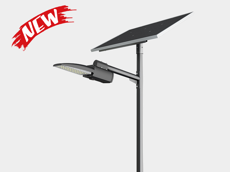
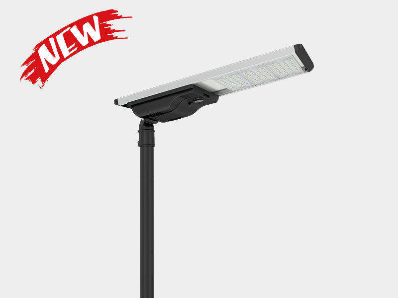
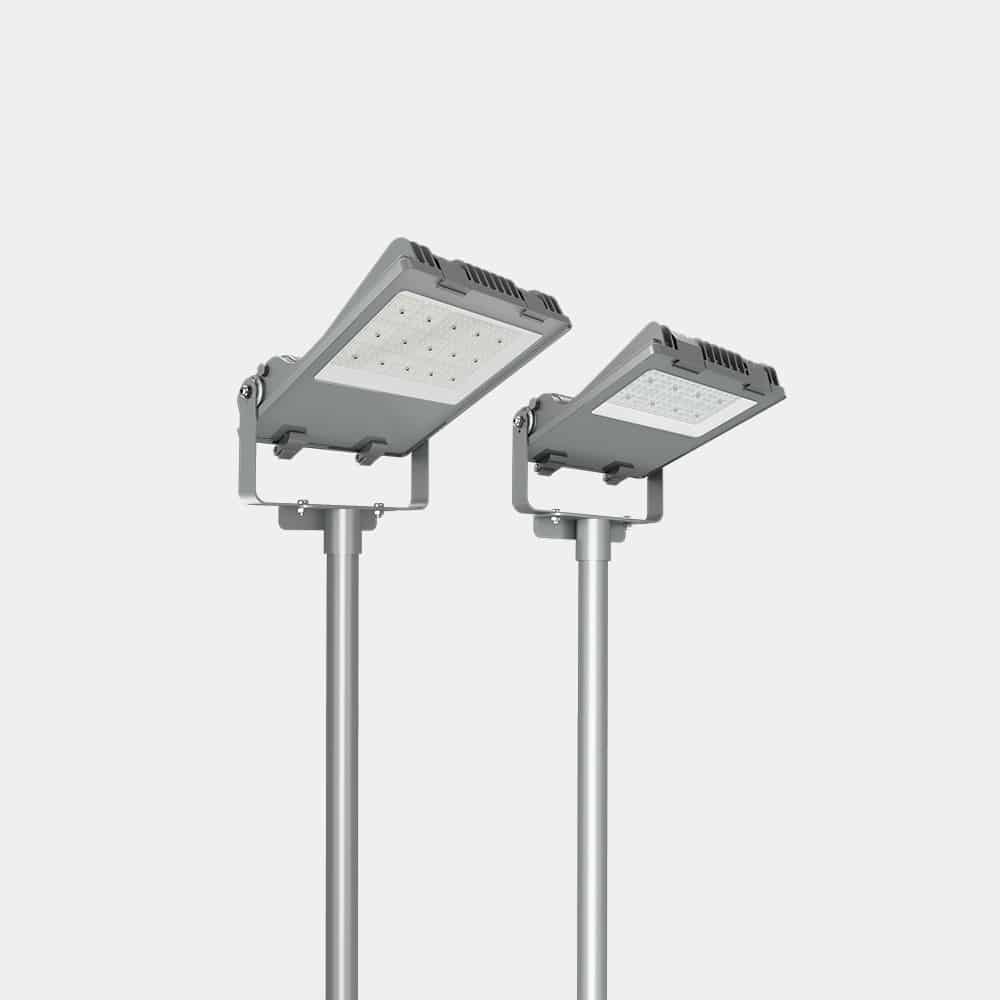
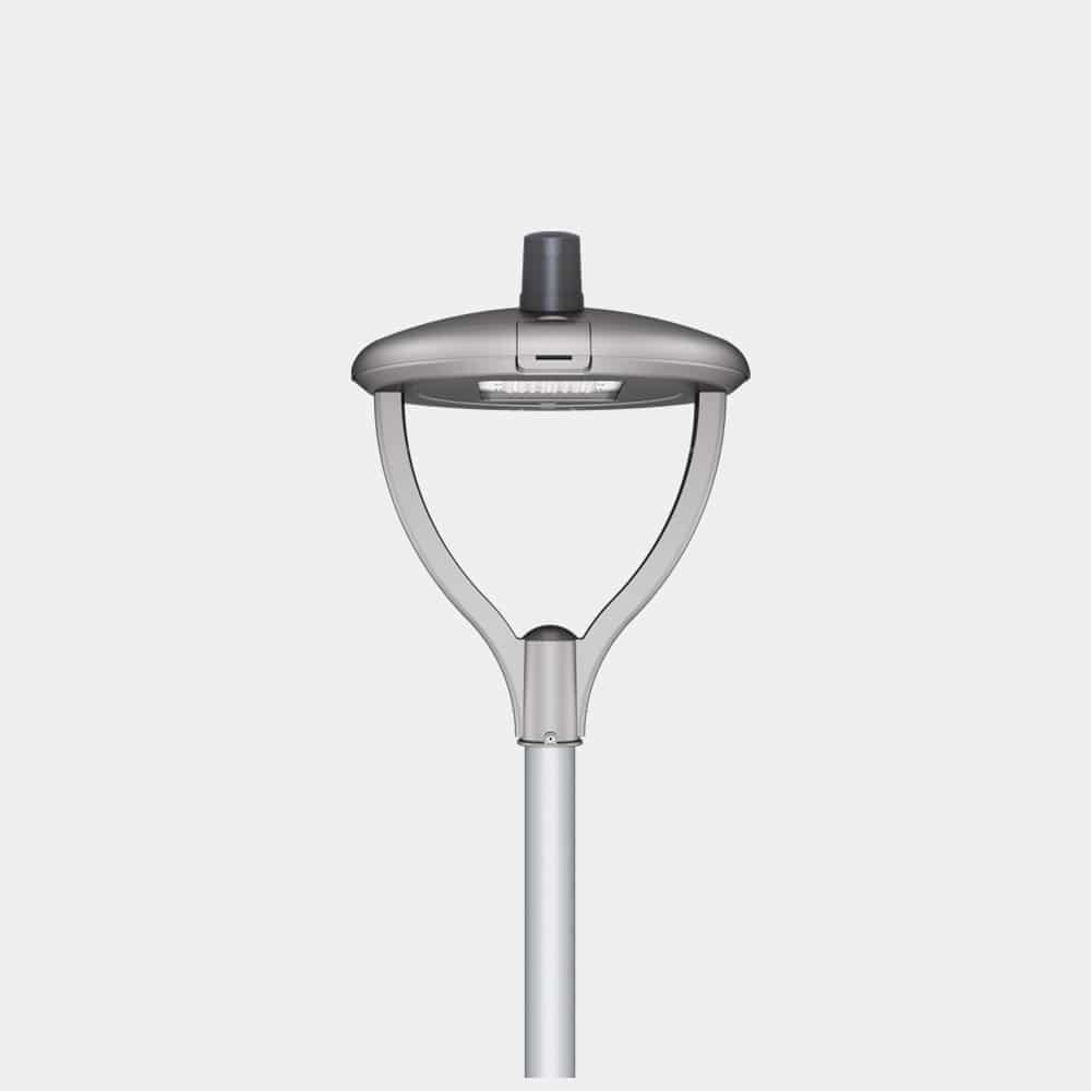
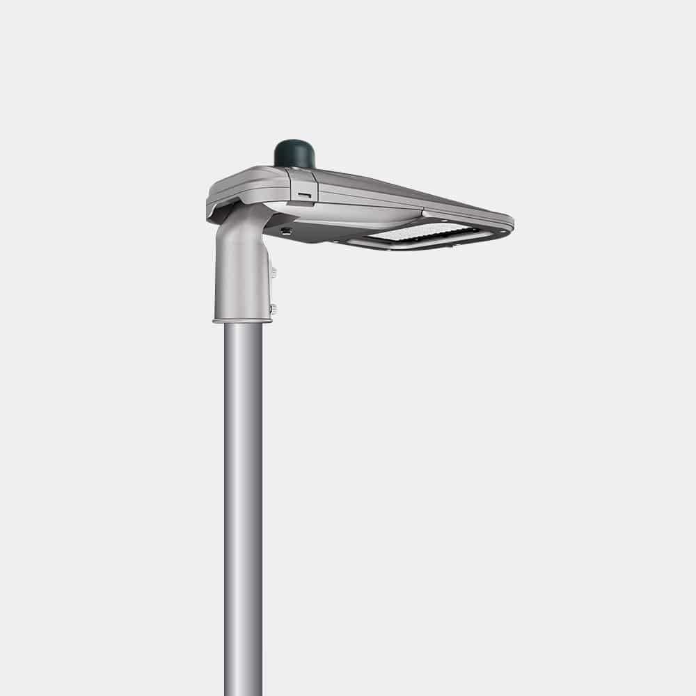
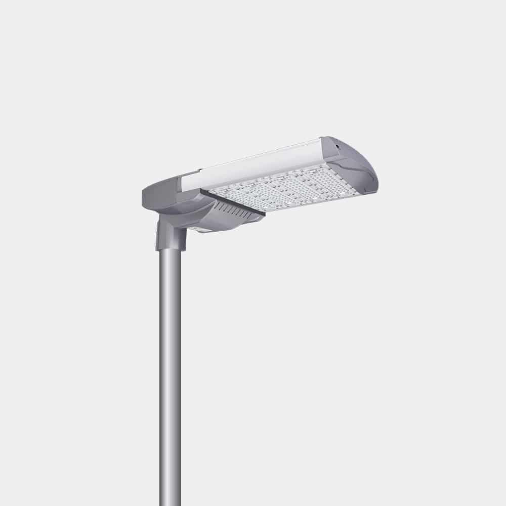
ZGSM solution with good LED light power factor
All ZGSM lamps have reasonable power and load configurations, and they all have good PF. Under normal circumstances, LED light power factor can reach 0.97 or even higher. If the dimming function is used, we also try to require the PF value to reach 0.9. The following are our best-selling lamps. If you are interested, you can also contact us.

Summary
Power factor is an important parameter that limits reactive power in power devices. It is an indication of the actual, apparent and reactive power in a comparison device. LED drivers have better performance on PF due to the use of their internal power factor corrector (PFC). Different LED driver suppliers have different capabilities in this area, and it is recommended that LED lamp manufacturers screen them. At the same time, we need to try to avoid low PF caused by unreasonable lamp configuration (too low load). In addition, the PF value of LED lamps differs greatly between full load and dimmed lighting systems. But ZGSM believes that during dimming, the lower LED light power factor relative to the input current consumed is not a problem.
FAQ
Related Posts

Guide for canopy light with battery backup
Tags:
Author

Taylor
Sales Engineer
I am Taylor, with 10 years of experience in lighting sales. Throughout my career, I have developed a deep understanding of the lighting industry and its products. My expertise lies in building strong relationships with clients, understanding their needs, and providing tailored lighting solutions that align with their requirements.