LED lens with different light distributions

Taylor
Introduction
The light distribution of a lamp refers to the distribution of light emitted by the light source in space. It involves the intensity, projection angle, and coverage of the light emitted by the light source in different directions. Different types of lamps with different LED lens have different light distribution characteristics to achieve different lighting effects. For example, the light distribution of a street light can be described as the intensity distribution of light in the horizontal and vertical directions to illuminate a long and wide road; the light distribution of a floodlight can be described as the intensity distribution of light in a spatial solid angle, which requires uniform illumination. Illuminating every corner of the space; the light distribution of floodlights is more concentrated than floodlights to illuminate specific areas in larger and farther areas. In addition, many lamps now use asymmetric light distribution to shine more light into specific directions or areas, such as sidewalks, billboards, walls, etc. These all involve the light distribution of lamps, so a special explanation is necessary.
Why care about light distribution?
Paying attention to the light distribution of your luminaire is crucial as it directly affects lighting levels, visual comfort and energy efficiency. Only by adopting a reasonable light distribution scheme can the best lighting effects (such as brightness/illuminance, uniformity and glare reduction) be achieved with minimal energy consumption. The importance of light distribution is explained in detail below.
Illumination intensity and uniformity: The distribution of light affects the level and uniformity of illumination within an area. Proper light distribution ensures the required intensity and uniformity of lighting in a space. For example, in road lighting, asymmetric light distribution using batwings can ensure that the road meets the brightness/illuminance and uniformity required by the project lighting standards. In contrast, a symmetrical floodlight distribution illuminates only a portion of the area beneath the fixture.
Visual comfort: Light distribution affects lighting comfort. Appropriate light distribution can avoid glare and improve visual comfort. Similarly, in road lighting, if the light distribution is unreasonable (the elevation angle is too large or the spectrum opening angle is too large), it will cause severe glare. However, reasonable light distribution can effectively reduce glare and reduce eye fatigue and discomfort for drivers and pedestrians.
Energy saving and efficiency improvement: Light distribution affects light utilization efficiency. Reasonable light distribution can achieve the required lighting effect with less energy consumption. For example, in stadium lighting, the use of asymmetric light distribution and NEMA Type 1-2 light distribution can illuminate all corners of the stadium. In contrast, floodlights with Type 6-7 light distribution cause energy waste and glare. A similar situation also exists in road lighting, which will be further elaborated on later.
How is the light distribution determined?
Light distribution testing of lamps usually needs to be carried out in a dark laboratory. By placing the luminaire on a rotating platform and using a light distribution meter, a device specifically designed to measure and record light intensity at different angles, the photometric data(Luminous Intensity Distribution) of the luminaire can be obtained to understand its light distribution. Below are two common measurement methods, Type B and Type C.
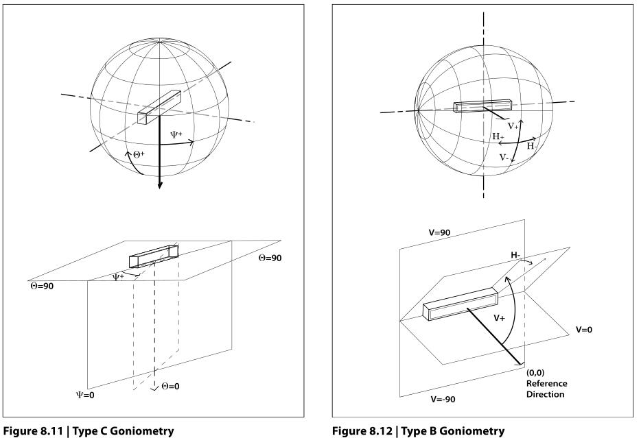
The luminous intensity distribution of a lamp determines its light distribution characteristics. The luminous intensity in all directions is specified in an angular coordinate system suitable for the luminaire and its general application. Most luminaires have a luminous intensity distribution specified by values in the directions given by the elevation and azimuth angles (θ, Ψ) of the spherical coordinate system. In Type C Goniometry, the elevation angle θ usually specifies the angle of the ray up or down along the vertical axis, while the azimuth angle Ψ specifies the angle of rotation along the vertical axis in the horizontal plane.
For some outdoor lamps, usually floodlights, some suppliers will choose the Type B method for measurement. The origin of the two angles (V, H) is the main aiming axis of the lamp and passes through the equator of the coordinate system. In this case, the two angles range from -90° to 90°. ZGSM mostly uses the Type C method. The following is our lamp using the Type C method to measure the light distribution of street lights.
Light distribution characteristics of street lights
IESNA determines the light distribution type of the lamp according to the shape of the illuminated area of the lamp. It is used for road and area lighting fixtures that require a complete analysis of light distribution, mainly street lights, post top lights and some floodlights. Although the installation methods of these lamps are different, we can all classify the light distribution of the lamp according to the guidance of IESNA. It mainly includes two parts: Lateral light distribution and Vertical light distribution. We introduce them respectively below.
Lateral light distribution
Lateral light distribution refers to the classification of how light from a fixture spreads across the street surface. In simpler terms, it defines the degree or coverage of lighting (across the road) that light provides across the entire street (street width). This classification is often used to evaluate the light installation height (MH) of the luminaire and the width of the road. It determines the light distribution type of the luminaire by analyzing the half-maximum candela locus. The following are the IES lateral distribution types and their definitions:
- Type I: Half-maximum candela trace falls between 1 MH on the house side and 1mh on the
- street side of the luminaire position.
- Type II: Half-maximum candela trace falls between 1 MH and 1.75 MH on the street side of the luminaire position.
- Type III: Half-maximum candela trace falls between 1.75 MH and 2.75 MH on the street side of the luminaire position.
- Type IV: Half-maximum candela trace falls beyond 2.75 MH on the street side of the luminaire position.
- Type V: Symmetrical, with a circular light distribution around the fixture location.
- Type VS: Symmetrical, with a square light distribution around the fixture location.
Different light distributions are suitable for different road lighting or area lighting. Luminaires commonly used for lighting main roads and branch roads, the most popular types are Type II and Type III. Type IV and V distributions are more commonly used for lighting parking lots or large areas. Type I is suitable for roads when the lamp is placed in the middle of a narrow road or a road with thick trees.
Vertical light distribution
Vertical light distribution refers to the classification of how light from a fixture spreads along both sides of the street. In simpler terms, it defines the degree or coverage of lighting (along the road) that light provides for an entire street. This classification is often used to evaluate the relationship between luminaire mounting height (MH) and pole spacing. It determines the light distribution type of the luminaire by analyzing the maximum candela locus. The following are the IES vertical distribution types and their definitions:
- Very Short: The maximum intensity point lands 0 to 1.0 MH each way longitudinally from the luminaire position.
- Short: The maximum intensity point lands between 1.0 MH and 2.25 MH each way longitudinally from the luminaire position.
- Medium: The maximum intensity point lands between 2.25 MH and 3.75 MH each way longitudinally from the luminaire position.
- Long: The maximum intensity point lands between 3.75 MH and 6.0 MH each way longitudinally from the luminaire position.
- Very Long: The maximum intensity point lands beyond 6.0 MH each way longitudinally from the luminaire position.
Different street light distribution applications
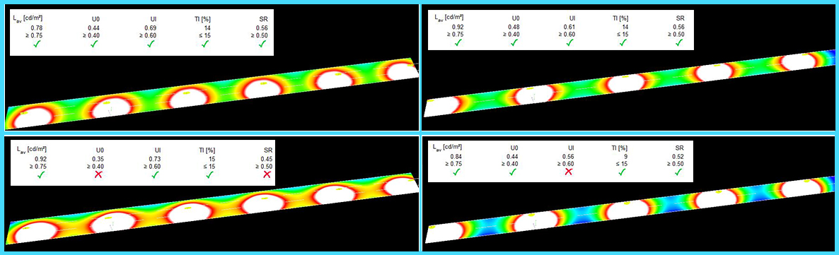
ZGSM analyzed different spectra of the Rifle series of street lights (T2M53007 and T3M53009) to study the contrast and uniformity effects of lateral light distribution. Taking into account the following road conditions: light pole height 8 meters, cantilever arm 1 meter, lamp spacing 30 meters, road width 10.5 meters, 3 lanes, lighting requirement M4a. As shown in the left picture below, T3M53009(upper left) can better direct light to the lane away from the lamp than T2M53007 to ensure that the illumination and uniformity meet the requirements of the M4a standard. And ZGSM analyzed different spectra of the Rifle series of street lights (T2S53001 and T3M53009) to study the impact of contrast and uniformity of vertical light distribution. Taking into account the following road conditions: light pole height 8 meters, cantilever arm 0.8 meters, lamp spacing 36 meters, road width 7 meters, 2 lanes, lighting requirement M4a. As shown on the right below, T3M53009(upper right) can better direct light away from the lamp than T2S53001 to ensure that illumination and uniformity meet the requirements of the M4a standard. On the contrary, T2S53001 is only suitable for situations where the distance between light poles is 30 meters.
Light distribution characteristics of floodlights
In the IES handbook, there are guidelines for defining flood light distribution. It is a lighting classification system defined by the National Electrical Manufacturers Association (NEMA, also issued standard of NEMA socket) based on the size of the beam angle produced by the lighting fixture. It is mainly used for sports lighting and floodlight fixtures. From the narrowest to the widest beam angle, it defines 7 distributions, types 1 to 7. This property uses beam angle and field angle to specify the light distribution of a fixture. The beam angle is the angle measured from the center of the light distribution of the lamp and refers to the angle corresponding to the light intensity falling to 50% of the maximum light intensity. In addition, NEMA also defines what the field angle is, which refers to the angle corresponding to the light intensity falling to 10% of the maximum light intensity.
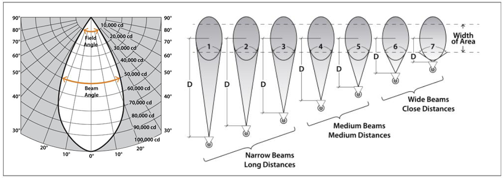
The table below shows beam angles and throw distances (recommended) for NEMA beam types.
| NEMA Type | Beam Spread (°) | Description | Projection distance (D) |
| 1 | 10° – 18° | Very Narrow | 240 ft and greater |
| 2 | > 18° – 29° | Narrow | 200 to 240 ft |
| 3 | > 29° – 46° | Medium Narrow | 175 to 200 ft |
| 4 | > 46° – 70° | Medium | 145 to 175 ft |
| 5 | > 70° – 100° | Medium Wide | 105 to 145 ft |
| 6 | > 100° – 130° | Wide | 80 to 105 ft |
| 7 | > 130°+ | Very Wide | Under 80 ft |
From this we know that NEMA indicates how wide or narrow the light cast by the floodlight is. Horizontal and vertical beam spread angles are used to distinguish NEMA types. For example: If a floodlight has a horizontal beam spread of 120° and a vertical beam spread of 120°, the NEMA type is 6 x 6. For a stadium light with a horizontal beam spread of 15° and a vertical beam span of 15°, the NEMA type is 2 x 2. For a stadium light with a horizontal beam spread of 30° and a vertical beam spread of 50°, the NEMA type is 3 x 4.
Different flood light distribution applications
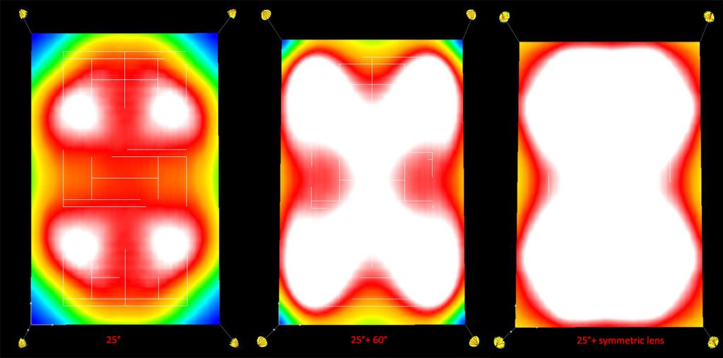
ZGSM used Dialux to simulate the lighting of tennis courts. There are three courts close together. The size of each tennis court is 36*18m. The light poles are at the four corners and the height of the light poles is 15 meters. The lighting requirements comply with Class II, that is, the illumination is 300lux and the uniformity is 0.7. We inserted the different light distribution of the Zoom series floodlights (25D53011, 60D53012 and 50 x120°) and analyzed the results. Dialux lighting results show that flood lights with 25 degrees + 60 degrees has better results, and 25 degrees + asymmetry has much better results. On the contrary, the uniformity of floodlights using only 25 degrees does not meet the requirements, and the light waste is serious.
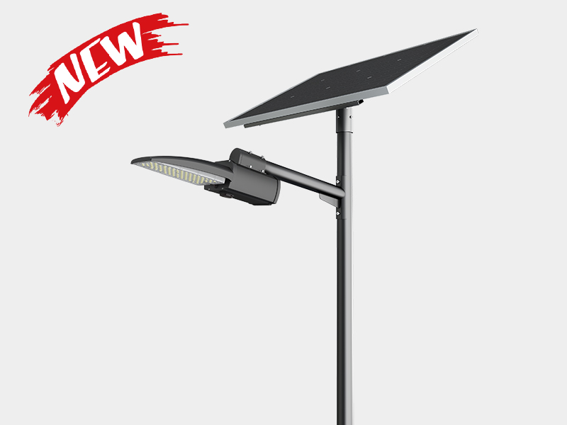
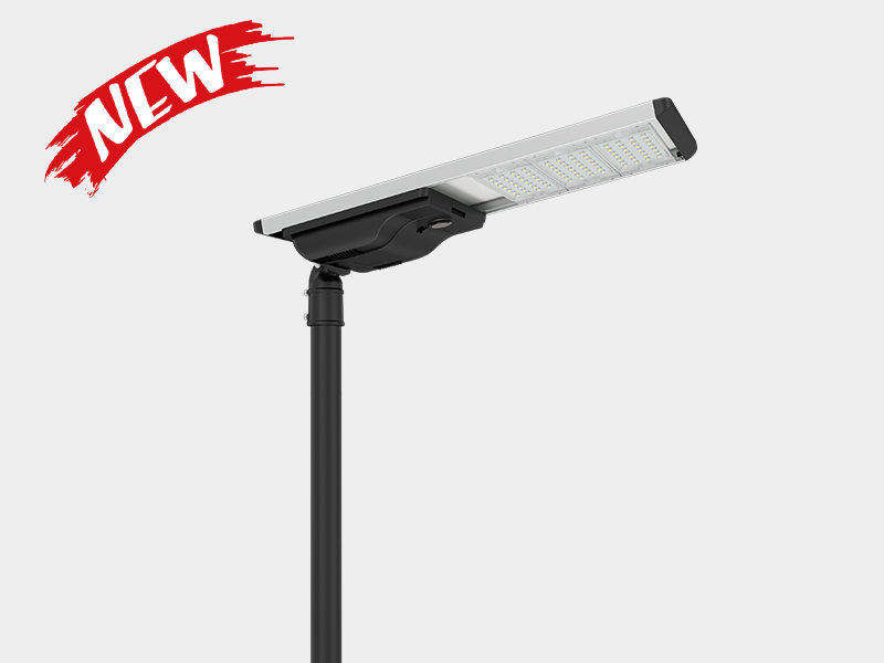
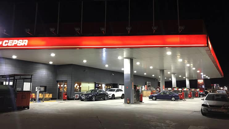
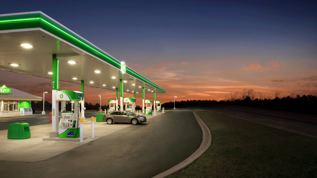
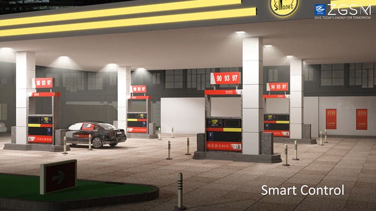
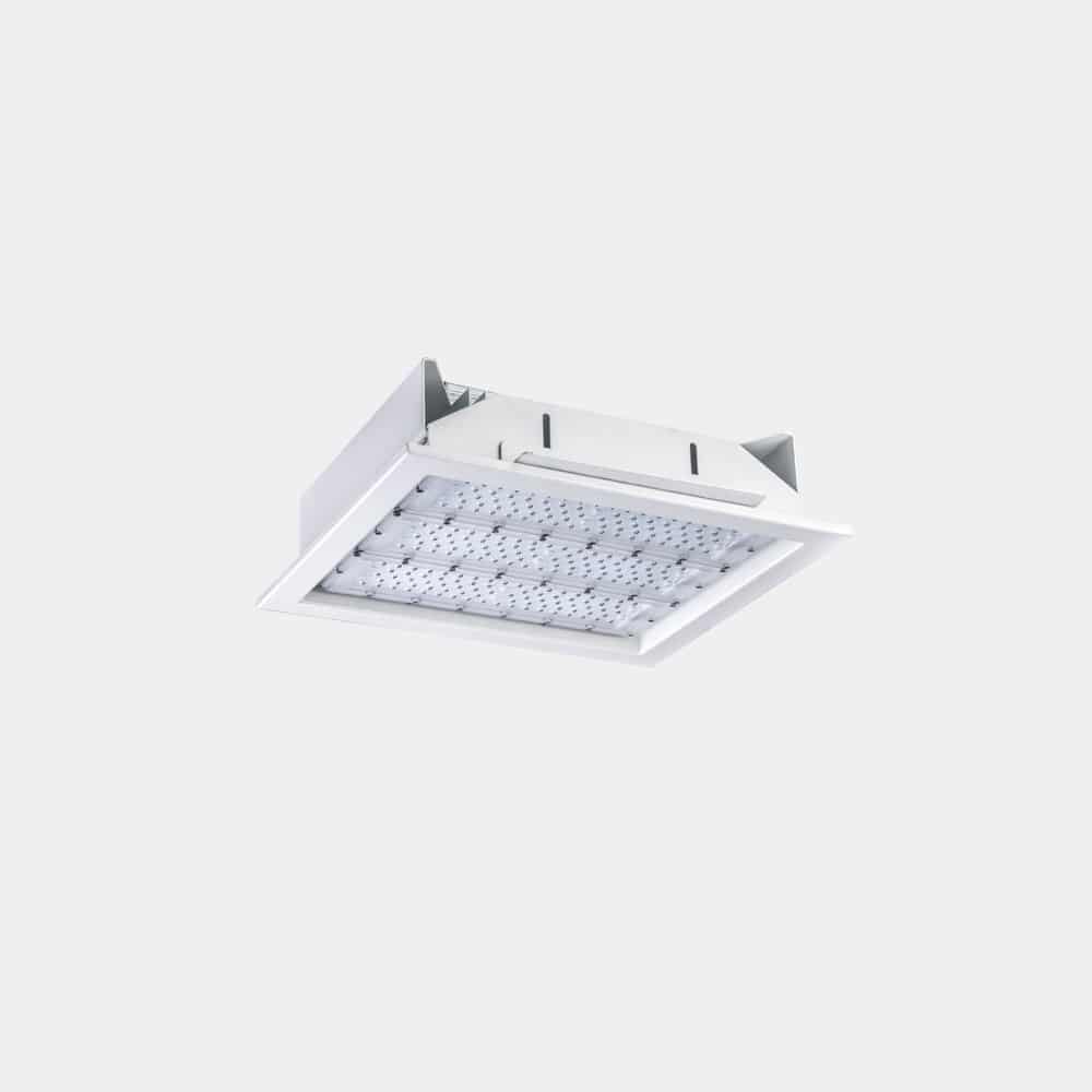
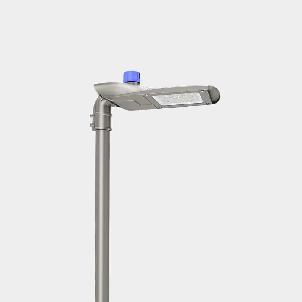
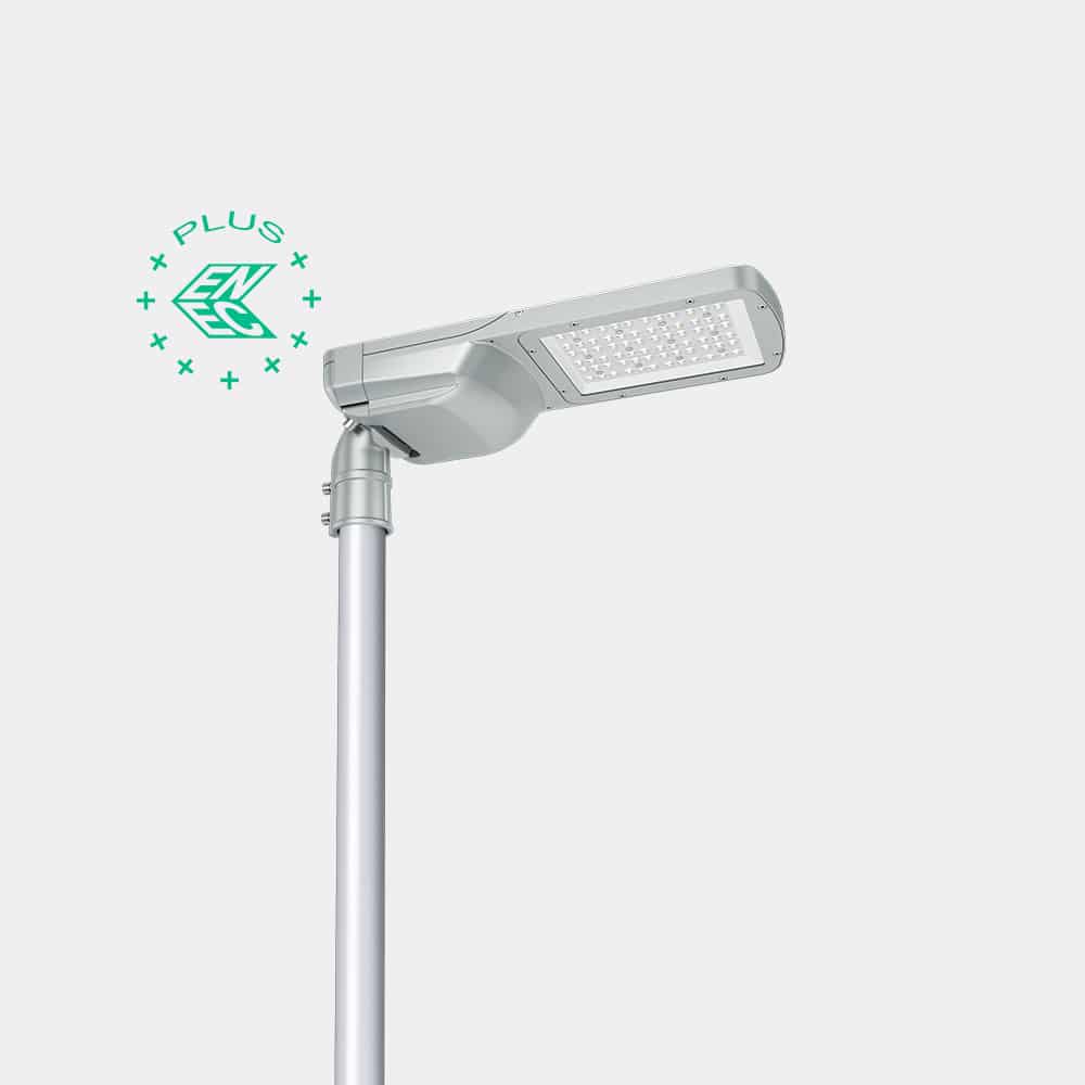
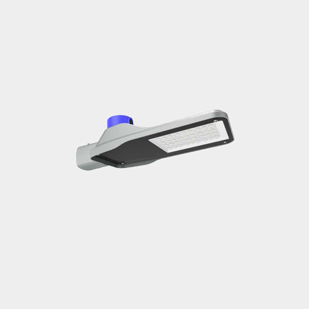
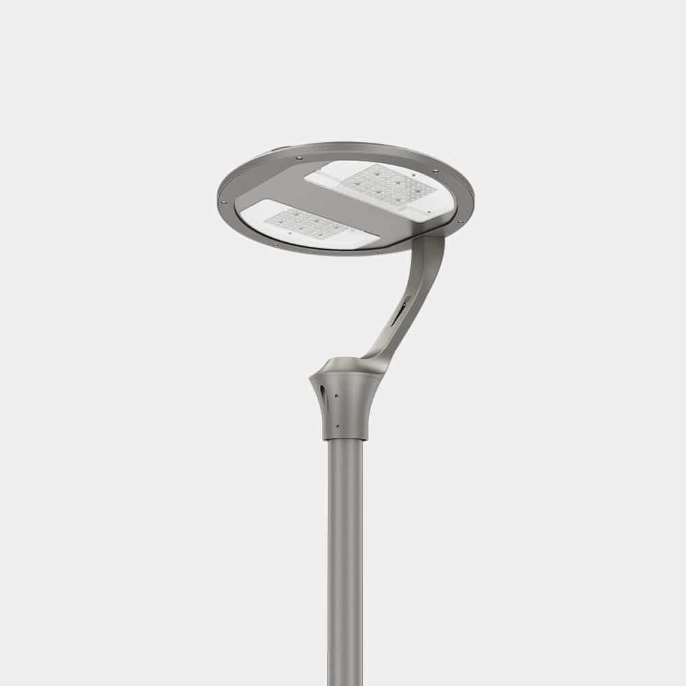
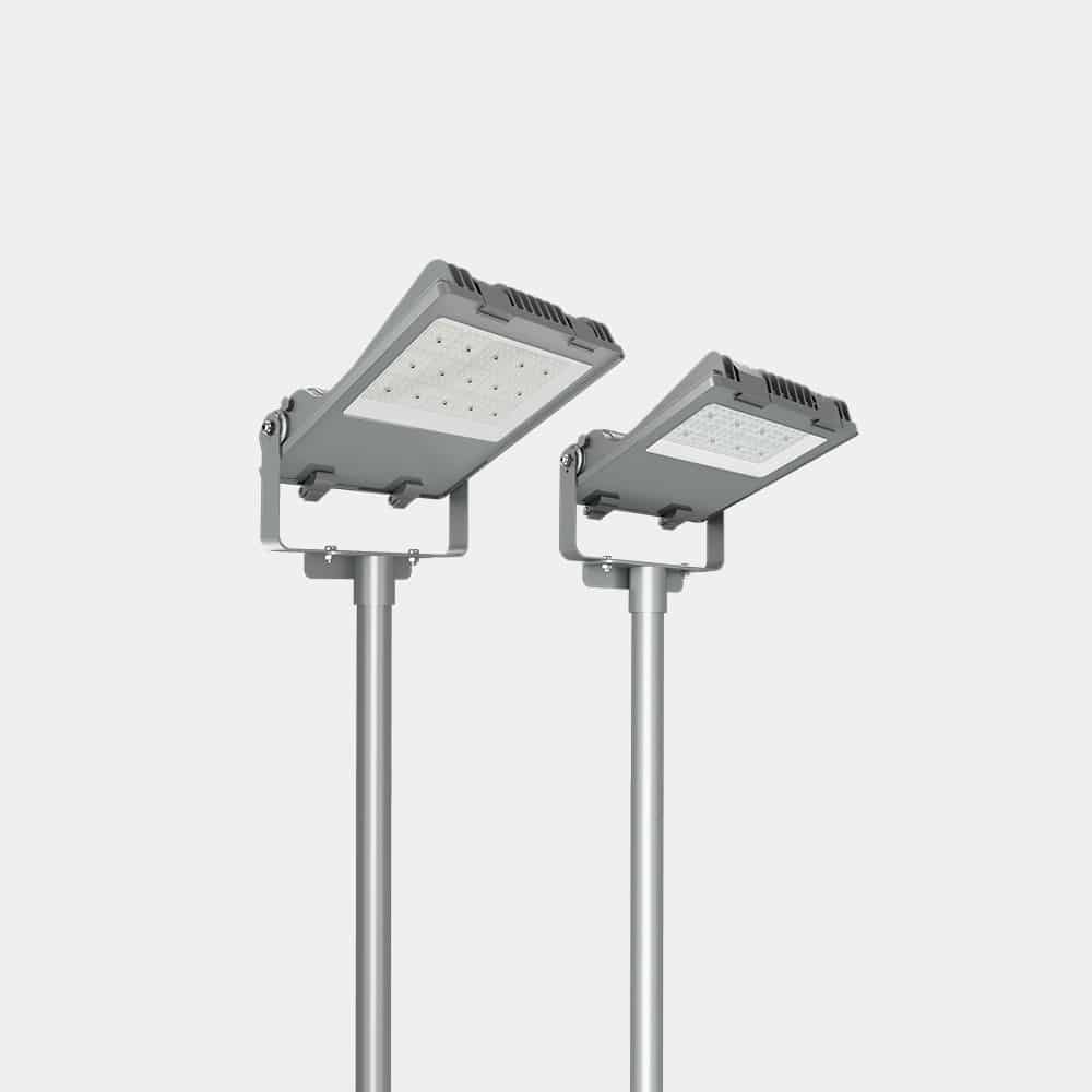
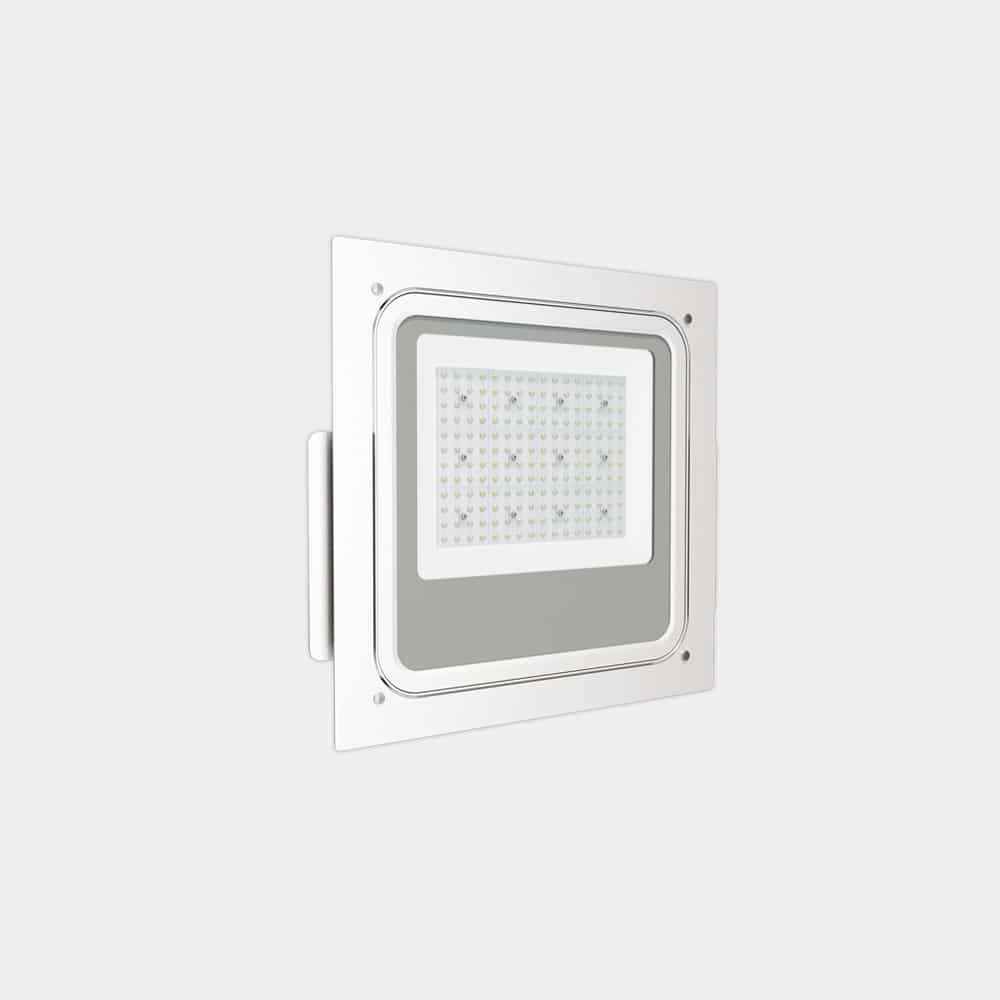
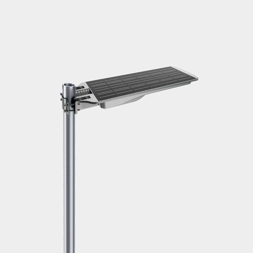
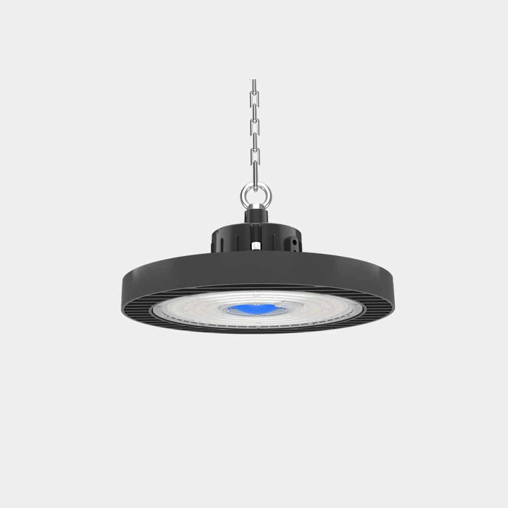
ZGSM LED lightings with different light distributions
All ZGSM lamps are equipped with various LED lenses to achieve diverse light distribution. This design allows our lamps to adapt to different road layouts, court layouts, and other outdoor locations. ZGSM’s LED products are listed below, including street lights, floodlights, stadium lights, gas station lights and solar street lights. If you are interested, please click on the relevant product for more information.
Summary
ZGSM believes that it is very meaningful to discuss the light distribution of lamps. Light distribution directly affects the actual lighting effect and visual comfort of this lamp. Reasonable light distribution can enable us to achieve reasonable, uniform and comfortable lighting at a smaller energy cost. This article mainly introduces how light distribution is measured and the basis for classifying light distribution of street lights and floodlights. At the same time, the application characteristics of different light distributions are also introduced in detail, such as Type II and Type III of street lights, as well as application examples of asymmetric and small-angle beam angle light distribution of floodlights. ZGSM also provides a variety of lamps with different light distributions (including street lights, floodlights and stadium lights) for customers to choose from. If you are interested in different lamps and different light distributions of lamps, please feel free to contact us.
FAQ
Related Posts
Guide for canopy light with battery backup
Tags:
Author
Taylor
Sales Engineer
I am Taylor, with 10 years of experience in lighting sales. Throughout my career, I have developed a deep understanding of the lighting industry and its products. My expertise lies in building strong relationships with clients, understanding their needs, and providing tailored lighting solutions that align with their requirements.